フリーストップヒンジの仕様 Specification of Friction Hinge(Free Stopping Hinge)
■フリーストップヒンジの選定の流れ
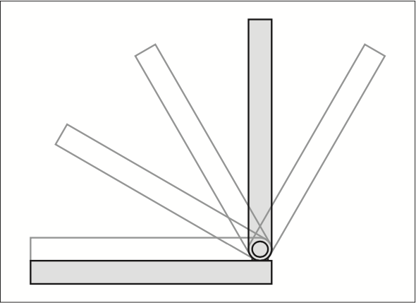
- 1.ご使用の目的から取付位置、操作位置を決定してください。
- 2.使用するヒンジの向きがチルト方向(軸を水平向きに取付)の場合は「チルト方向のトルク値計算」を基に選定をおこなうことが出来ます。ヒンジの向きがスイベル方向(軸を垂直向きに取付)の場合はご相談ください。
- 3.「チルト方向のトルク値計算」は理論値になります。実装にて開閉時の操作感等の確認をおこなってください。
■How to select Friction Hinge(Free Stopping Hinge)
- Select by application.
- When you use free stopping hinge laterally(install the shaft in horizontal direction), you can select hinges according to[torque calculation according to tilt direction]. If you want to use hinge longitudinally(install the shaft in vertical direction), please contact us.
- [torque calculation according to tilt direction]is only the theoretical value, please confirm the operational feeling when using.
●仕様
※特定の商品を除き、記載のない限り、商品全般、以下の仕様となります。
- 屋内仕様です。耐水性及び防塵性はありません。
- 設定トルクは、常温環境(25℃±5℃)の値です。
- 温度特性として、初期トルクの±30%以内で、一般的に温度が上がるとトルクは下がり、温度が下がるとトルクは上がります。
- 常温環境にて、20,000 回の耐久試験をしています。
●Specification
- For indoor use only. No waterproof or dustproof.
- Initial torque: 25℃ ±5℃ at room temperature.
- As temperature characteristics, the value of torque may change within ±30℃ of the initial torque.
- Durability: 20,000 cycles.
※Except for specific products, unless otherwise indicated, standard specification is as follows.
●注意事項
- 蓋 1 枚に対し、2 個以下のヒンジでご使用ください。
ヒンジ 1 個で使用する場合は、同軸上に軸受けを設けてください。 - 偏荷重が掛からないようにご使用ください。
- 潤滑油を差したり、油がかかる箇所には使用しないでください。
- 熱影響を受ける処置は行わないでください(溶接、焼付塗装等)。
- 連続動作(短時間での繰り返し動作)はしないでください。
- ダンパー効果、減速効果を期待した使い方はしないでください。
- ヒンジの取付用穴は、全箇所使用して固定してください。
- 操作感は、取付物の重量や重心の位置により異なるため、必ず実装状態にてご確認ください。
- センターずれをおこす可能性があるため、異なる品番を同軸上で使用しないでください。
●Note
- Use no more than 2 pieces per a lid.
- Apply bearing to the shaft when you use one piece of hinge per a lid.
- Avoid offset load.
- Avoid using around oily condition.
- Do not fix by welding.
- Do not use in the continuous motion application.
- Avoid applications where the damper is required.
- Fix every hole for installation.
- Do NOT use different hinges together.
実機使用例
Example
車載モニター(6.5 インチ)
Car Monitor(6.5 Inch)
Car Monitor(6.5 Inch)
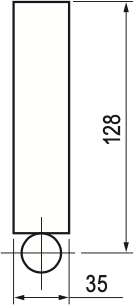
重量 約600g
Net Weight Approx.600g
ヒンジトルク 1.37N・m(14kgf・cm) 1個
Hinge Torque 1.37N・m(14kgf・cm) One
Operation Power(Vertical Position, upper end)
F = 1.37N・m / 0.128m
= 10.7N
端末タッチパネル
Terminal Touch Panel
Terminal Touch Panel
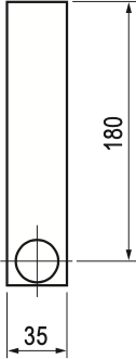
重量 約1kg
Net Weight Approx.1kg
ヒンジトルク 1.08N・m(11kgf・cm) 2個
Hinge Torque 1.08N・m(11kgf・cm) Two
Operation Power(Vertical Position, upper end)
F = (1.08N・m × 2) / 0.18m
= 12N
車載モニター
Car Monitor
Car Monitor
重量 約500g
Net Weight Approx.500g
ヒンジトルク 0.34N・m(3.5kgf・cm) 2個
Hinge Torque 0.34N・m(3.5kgf・cm) Two
Operation Power(Vertical Position, upper end)
F = (0.34N・m × 2) / 0.078m
= 8.7N
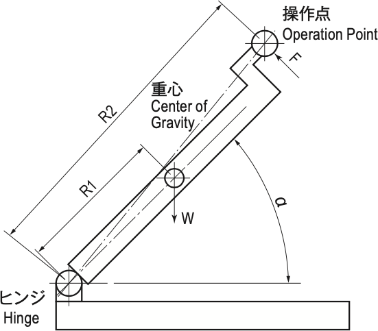
●チルト方向のトルク値計算 Torque calculation according to tilt direction
※ソフトダウンヒンジ等は、計算が異なります。
※ The calculation is different for dampended hinge.
トルク関数計算式
| 重心半径 Center of Gravity Radius | R1 m |
| 操作半径 Operation Radius | R2 m |
| 重量 Net Weight | W kg |
| 操作力 Operation Power | F N |
| 重心角度 Center Gravity Angle | α 度 |
| 重量トルク Weight Torque | T1 N・m |
| 操作トルク Operation Torque | T2 N・m |
| ヒンジトルク Hinge Torque | T3 N・m |
| 重力加速度 Weight Accelerated Velocity | G=9.81m/sec2 |
| 重量トルク Weight Torque | T1=W×G×R1cosα |
| 操作トルク Operation Torque | T2=F×R2 |
| 閉方向操作トルク Closing Direction Operation Torque | T2=T3-T1 |
| 開方向操作トルク Opening Direction Operation Torque | T2=T3+T1 |
| 閉方向操作力 Closing Direction Operation Power | F=(T3-T1)/R2 |
| 開方向操作力 Opening Direction Operation Power | F=(T3+T1)/R2 |