技術資料・注意事項トップへ Technical information
Back To Top
MENU

ガススプリングの仕様・注意事項・選定方法 Specification, Note and How to Select Gas Spring

※特定の商品を除き、 記載の無い限り、 商品全般は以下の仕様となります。 ご使用前に必ずご一読、ご理解いただいた上でお使いください。

Specification of all gas springs are shown below unless otherwise specified. Please make sure to check the following information before use.

日本語
ENGLISH
仕様
ガススプリング用ブラケットとの併用を推奨いたします。
取り付けが簡単に行えます。
ガススプリングブラケット/取付ボルト(TM-171)
対象型番:TM-149・150・361・363・364・365・369
ブラケット(H型)(TM-247)
対象型番:TM-151・370・371
ガススプリング用脱着ブラケット(TM-326)
対象型番:TM-149-50-5・149-50-10・149-70-5・149-70-10・
TM-149-80-5・149-80-10・149-90-5・149-90-10・
TM-149-100-5・149-100-10・
TM-364-50-10・364-80-10・364-100-10
取付金具/ブラケット(TM-279・280)
対象型番:TM-276・277・278
Specification
Recommended to use with Brackets. Easy to install.
Bracket / Bolt (TM-171)
Applicable Model No. : TM-149・150・
TM-361・363・364・365・369
Bracket (Type H)
Applicable Model No. : TM-151・370・371
Removable Bracket for Gas Spring (TM-326)
Applicable Model No. : TM-149-50-5・149-50-10・149-70-5・
TM-149-70-10・149-80-5・149-80-10・
TM-149-90-5・149-90-10・
TM-149-100-5・149-100-10・
TM-364-50-10・364-80-10・
TM-364-100-10
Rod Eye / Bracket (TM-279・280)
Applicable Model No. : TM-276・277・278
注意事項

・ピストンロッドを下側にして取り付けてください。

・分解したり火中に投じないでください。高圧ガスが封入されておりますので、非常に危険です。

・雨や水の掛かる場所、ホコリの多い場所での使用はさけてください。
環境によってはオイル漏れや作動不良の原因となります。

・ピストンロッド及びシリンダーに傷・打痕・曲がりが生じるような、衝撃や荷重を加えないでください。
変形によりオイル漏れ、作動不良、破損の原因となります。

・ピストンロッドに塗料やビニール等の異物が付着しないようにしてください。
伸縮時にシリンダー内部に入り込みますと、オイル漏れや作動不良の原因となります。

・ピストンロッド(摺動部)に注油はいっさい行わないでください。
注油をするとシール性が悪くなり、反発力の低下やオイル漏れの原因となります。

・伸長方向に引っ張る力を加えないで下さい。引っ張り力は許容しておりません。

・最伸長の状態で回転させないで下さい。回転させる際はピストンロッドを圧縮した状態で行ってください。
最伸長以上に伸びる力が掛かりますと、破損の原因となります。

・ガススプリングを扉や蓋の長時間保持用として使用しないでください。突風等、 イレギュラーな外力が掛かった際、 ガス抜けにより突然蓋が閉まる可能性があり危険です。支え棒等、 ストッパーとの併用を推奨いたします。

・故障が起きた場合は使用を中止し、メーカーまたは購入元へご連絡ください。

Note

・Piston rod should be installed downward.

・Do not disassemble and keep away from fire. It is extremely dangerous because higher pressure gas is filled in Gas Spring.

・Avoid using Gas Spring where rain or water splash or where dust lies.
It causes oil leaks and malfunction depending on environment.

・Do not apply any shock on Gas Spring to prevent any cut or bend of prison rod.
It causes oil leaks, malfunction and damage by deformation.

・Piston rod should be kept away from any foreign matter such as paint or vinyl.
It causes oil leaks and malfunction if they get into cylinder inside.

・Do not lubricate piston rod (sliding portion).
It causes reducing reaction and oil leaks because of degradation of seal performance and oil leaks.

・Do not apply tension in the direction of extension.

・Piston rod and cylinder should not be rotated when Gas Spring is fully extended.
It causes breakage if extended power is applied more that it is fully extended.

・Avoid using Gas Spring to keep a door or lid open for a long time. It is dangerous since the lid might be closed in sudden by degassing when sudden foreign power is applied. It is recommended to use with stopper such as supporting rod.

・In case of malfunction, stop using it and contact the maker or supplier.
ガススプリングの計算手順 Calculation Procedure of Gas Spring

日本語
ENGLISH
1. はじめに
使用用途から蓋(扉)の開閉角度、本体及び蓋(扉)のガススプリングを取り付ける位置を決定してください。
この時、必要となるガススプリングの最伸長は、蓋(扉)が最も開いた状態(開状態)での本体 - 蓋(扉)間の取付位置の直線距離であり、ガススプリングのストロークは、開状態と蓋(扉)を閉じた状態(閉状態)の各直線距離の差分になります。
次に必要となる最伸長及びストロークを満たすガススプリングを選んでください。また、ガススプリングの使用温度範囲は -20℃~+80℃になります。使用温度範囲外での使用はしないでください。
1. Introduction
Please determine the installation position for the lid (door) of gas spring, and opening/closing angle according to the use application.
The maximum extension of the needed gas spring will be a direct distance between the body and the lid (door) at the most opened state.
The stoke of the gas spring will be the difference between each direct distance when the lid is opened / closed.
As next step, please choose the gas spring which meet the demand of stroke and the maximum extension.
The operating temperature range for the gas spring will be -20℃ to +80℃ .
Please do not use it at beyond the above temperature.
2. 開状態(閉動作時)での蓋(扉)の状態と操作力
T1 = W × g × L1 ・・・(1)
T2 = F × n × L2 ・・・(2)
計算式(1)及び(2)から蓋(扉)トルクT1 及びダンパートルクT2 の値を求めることができます。この時、W[kg] は蓋(扉)重量、n は本数になります(g[m/s2] は重力加速度を示し、定数 9.8 になります)。
F[N] はガススプリングの反発力を示し、この値はストロークによって変化します。反
発力を求める方法として、グラフ作成による方法と計算による方法をご紹介します。
2. The condition of the lid(door)and operational ability when it moves to closing direction from the opening state.
Able to evaluate the value of T1(torque for the lid/door) and T2(torque for the dumper) by the calculation formula(1)and(2).
In this case, W [kg] indicates the lid weights, and n indicates the number of gaskets.(g [m/s2] indicates the acceleration of gravity, and the constant number will be 9.8)
F [N] indicates the reaction of the gas spring, and it will be changed depending on the stroke.
Please refer to the below 2 ways for evaluating the value of reaction.

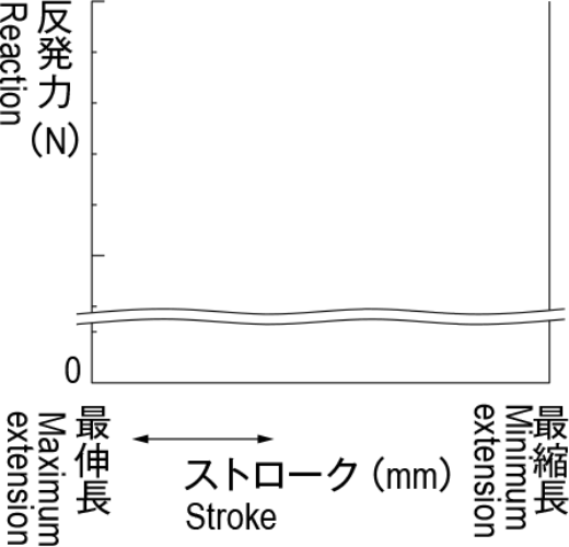
グラフ作成による方法
Graph making

1.

横軸をストローク、縦軸を反発力としたグラフをつくります。

Making a graph which sets ahorizontal axis as stroke, andvertical axis as reaction.
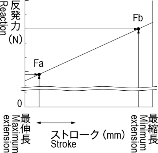
2.

商品毎に記載されている FaとFb の数値をグラフ上にプロットし、2 点を通過する直線を最伸長と最縮長間で引いてください。

Please plot the value of Fa and Fb (which is indicated on each product) on the graph, and draw a straight line which go through both points Fa and Fb between the maximum extension to the minimum extension.
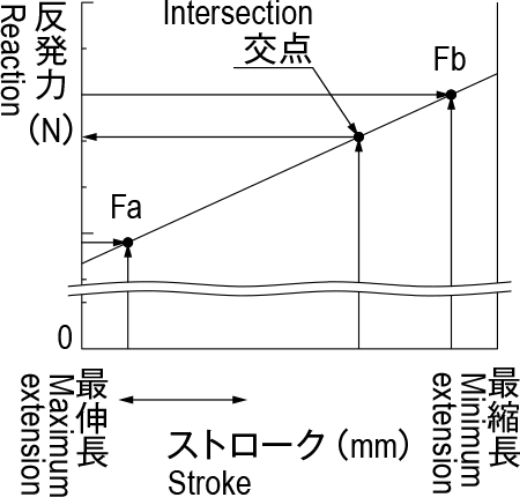
3.

横軸上で必要としているストロークから縦軸と平行に直線を引き、Fa-Fb間線との交点を見つけます。その交点から横軸と平行に直線を引き、縦軸上の交点が反発力となります。

Draw a straight line from the point of needed stroke which is indicated on horizontal axis to the vertical direction, and find an intersection that crosses with another straight line between points Fa and Fb. Then, draw another straight line from the intersection to horizontal direction and find an intersection that crosses with the vertical axis. It indicates the value of reaction.

※ TM-276,TM-277,TM-278 をご使用の際は、Fa を F1、Fb を F2としてグラフを作成してください。

※ When you use TM-276, TM-277, or TM-278, please indicates F1 and F2 instead of Fa and Fb on the graph.

日本語
ENGLISH
計算による方法
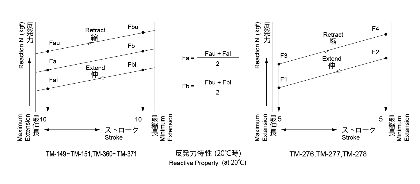
計算式(3)及び(3)' を用いることで反発力を求めることができます。
TM-149~151, TM-360~371 の場合
TM-276, TM-277, TM-278 の場合
カタログでは 20℃の反発力になります。温度が 10℃変化する(高温、低温とも)毎に反発力は約 3.4% 増減しますので、使用条件に合わせて計算をしてください。
計算の結果、"T1 < T2" の状態であれば、蓋(扉)は開いた状態で維持されます。T1 の値が大きくなってしまった場合は、手順 1. にて決定した条件を変更し、T2 が大きくなるようにしてください。
また、計算式(4)は閉じるのに必要な力(操作力)になります。
Calculating
Able to evaluate the value of the reaction by using either calculation formula
(3) or (3)'.


Reaction on this catalog is indicated at 20℃ in the area. Reaction increases and decreases 3.4% every 10 ℃ (both high and low temperatures). Please calculate depending on the condition for use.
If it becomes "T1 < T2" as a result of the calculation, the lid (door) remains as the condition that the lid (door) is opened. In the case that T1 is bigger than T2, plaese change the condition decided in Step 1 to make T2 bigger.
Calculating formula (4) shows operational ability needed when it is closed.
日本語
ENGLISH
3. 閉状態(開動作時)での蓋(扉)の状態と操作力
開状態と同様の計算式(1)及び(2)でトルクT1 及び T2 の値を求めることができます。
計算の結果、"T1 > T2" の状態であれば、蓋(扉)は開きません。
T2 の値が大きくなってしまった場合は、蓋止やマグネットキャッチ等にて開き止めを施すことでご使用することができます。
また、計算式(5)は開くのに必要な操作力になります。
3. The condition of the lid(door)and operational ability when it moves to closing direction from the opening state.
Can be derived the value of Torque T1 and T2 through calculating formula of(1)and(2)as well as when it is opened.
If it becomes "T1 > T2" as a result of the calculation, the lid(door)is not opened.
In the case that T2 is bigger than T1, it is available for use a cover latch and magnet catch as an opening stopper.
Calculating formula(5)shows operational ability needed when it is opened.
4. 開閉途中での蓋(扉)の状態
手順 2. 及び 3. で紹介しましたトルクT1 及び T2 の計算式を用いることで、特定角度での蓋(扉)の動きを確認することができます。
T1 < T2 : 蓋(扉)は開状態に向けて動きます。
T1 > T2 : 蓋(扉)は閉状態に向けて動きます。
T1 = T2 : 蓋(扉)は計算の際に使用した角度を維持します。
4. The condition of the lid(door)when it is opened and closed
It is possible to confirm the movement of the lid(door)in the specific angle through calculating formula of Toruque T1 and T2 introduced in Step 2 and Step 3
T1 < T2 : The lid(door)moves to opening direction.
T1 > T2 : The lid(door)moves to closing direction.
T1 = T2 : The lid(door)remains the angle used in calculation.
5. おわりに
手順 2. 及び 3. の計算結果から、1 度の計算で適切条件を満たす事は難しいです。
そのため、適切な結果を得られない場合は手順 1. にて決定しました条件(特にガススプリングの反発力、長さ、取付位置)を変更し、計算を繰り返して適切条件をお求めください。
また、本選定は計算に基づく理論値となります。最終的には実装にて取付側の強度等含め、ご判断をしてください。
5. Lastly
It is difficult to fulfill the suitable condition on the signal calculation through the result of step 2 and 3. Therefore, please derive the suitable condition to repeat calculation after changing the condition(esp. the reaction, length, installation position)decided at Step 1 when the proper result is not obtained. Also, this method of selection is based only on calculation. Please confirm and consider the strength of installed side with acutual equipment.

L1 m : 回転中心 - 重心位置の水平距離
Rotation Center - Horizonal Distance of Gas Spring
L2 m : 回転中心 - ガススプリングの垂直距離
Rotation Center - Horizonal Distance of Gas Spring
L3 m : 回転中心 - 操作位置の距離
Rotation Center - Distance of Operation Position
T1 N・m : 蓋(扉)重量トルク
Lid (Door) Net Weight Torque
T2 N・m : ダンパートルク
Damper Torque
T3 N : 操作力
Operational Ability
ガススプリングの仕様・注意事項・選定方法 Specification, Note and How to Select Gas Spring

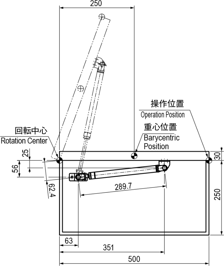
■上蓋計算例

取付仕様
蓋重量 =20kg
使用ガススプリング:TM-150-100-20
使用本数:2 本
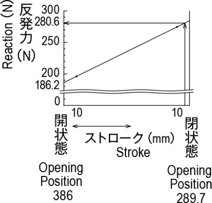
Calculation Example of Top Lid
Instrallation Specification
Lid Net Weight = 20 kg
Model No. : TM-150-100-20
Number of Gas Springs : Two

閉状態(開動作時)での蓋(扉)の状態と操作力

The condition of the lid(door)and operational ability when it moves to opening direction from the closing state.
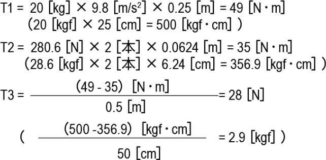
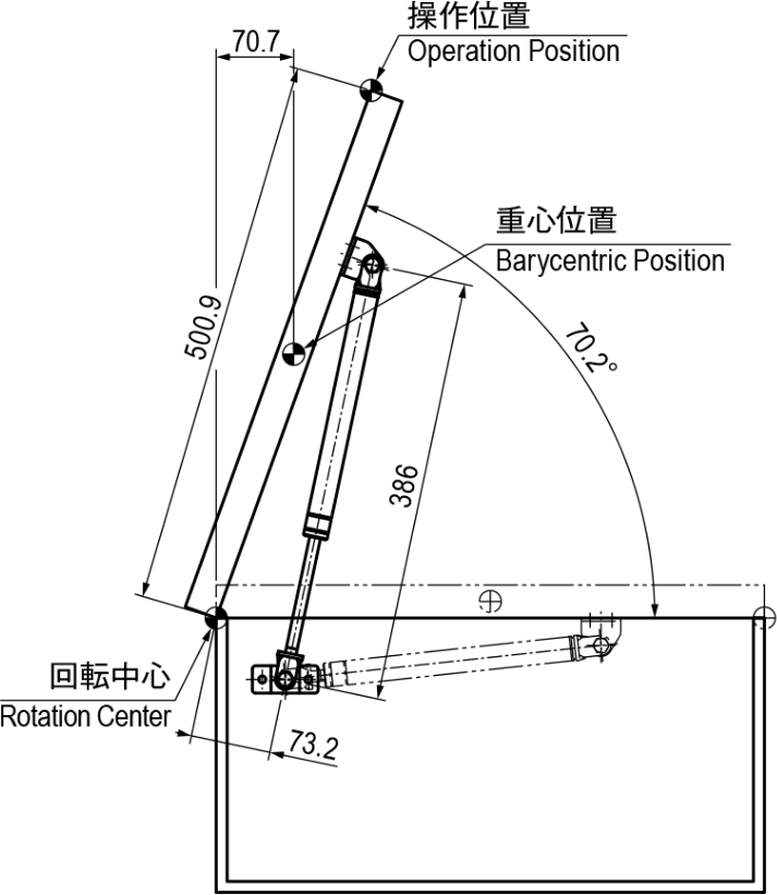
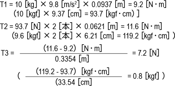
開状態(閉動作時)での蓋(扉)の状態と操作力

The condition of the lid(door)and operational ability when it moves to closing direction from the opening state.
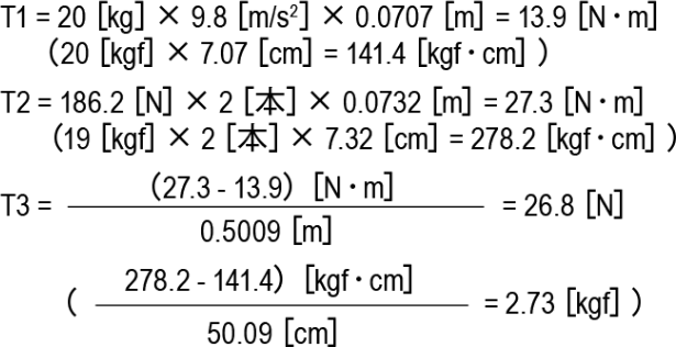
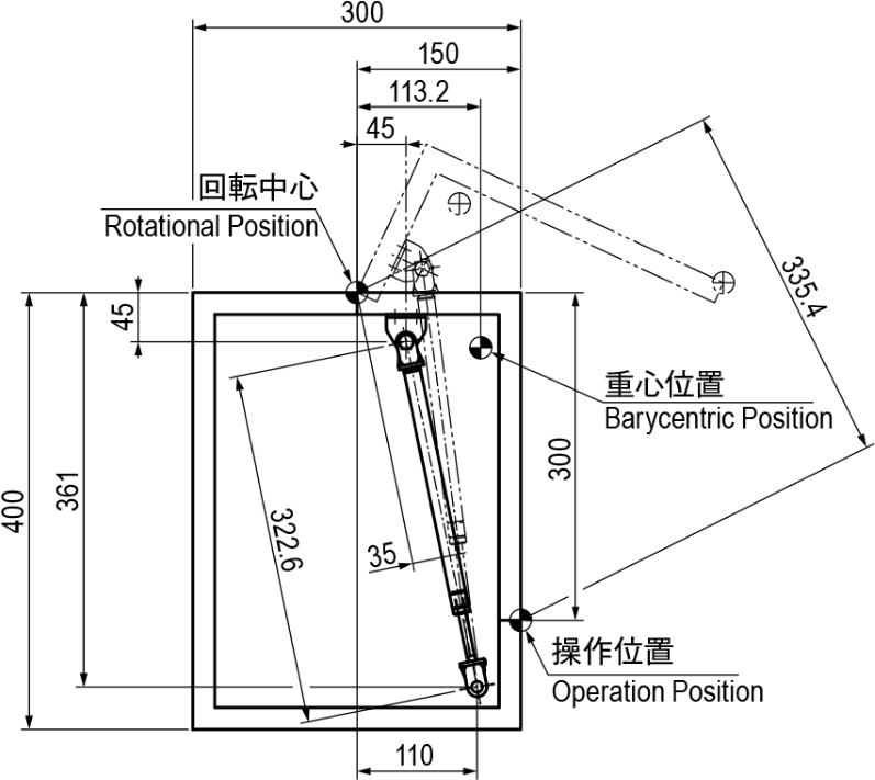
■前蓋計算例

取付仕様
蓋重量 =10kg
使用ガススプリング:TM-149-100-10
使用本数:2 本
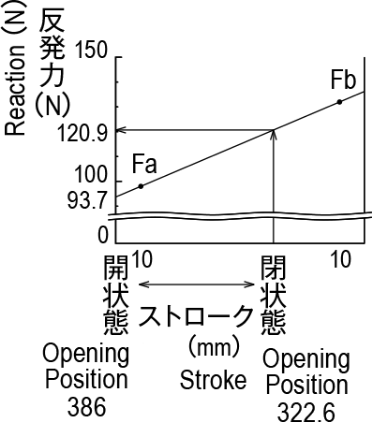
Calculation Example of Front Lid
Instrallation Specification
Lid Weights = 10kg
Model No. : TM-149-100-10
Number of Gas Spring : Two

閉状態(開動作時)での蓋(扉)の状態と操作力

Condition of the lid(door)and the operational ability when it moves to opening direction from the closing state.
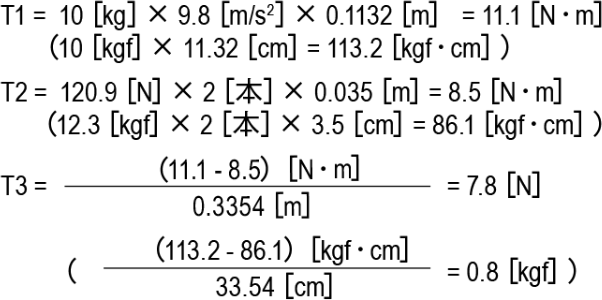
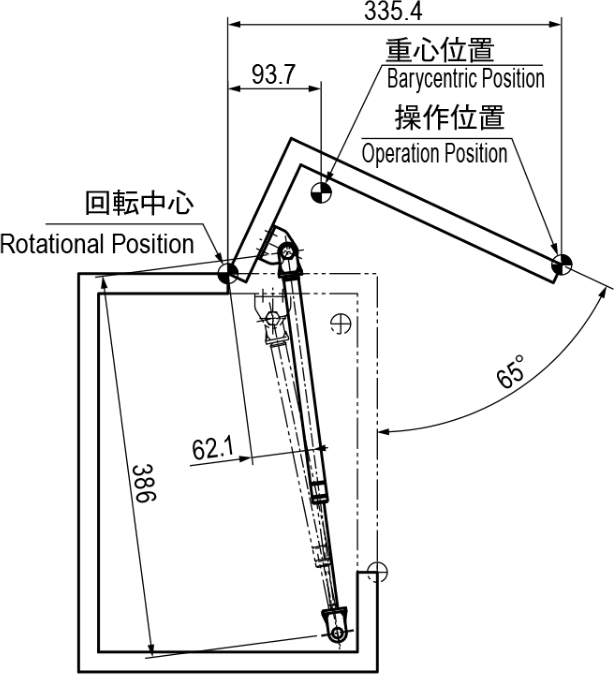
開状態(閉動作時)での蓋(扉)の状態と操作力

Condition of the lid(door)and the operatonal ability when it moves to closing direction from the opening state.